Introducing Bit+ x Arduino At Heart — a coding experience for students of all ages and expertise levels that provides frustration-free coding experiences. Be up and running in minutes and unlock a new world of critical-thinking, problem solving and developing future-ready skills.

What are the advantages of Bit+ x Arduino At Heart?

  • Arduino® community
  • Easy-to-learn, powerful programming language
  • Coding versatility
Ozobot Bit programmable coding robot by Ozobot and Arduino at Heart

Ozobot Bit+ is now Arduino At Heart certified, enabling full compatibility with Arduino®.

Ozobot Bit+, a feature-packed programmable coding robot, aligns perfectly with the Arduino® ecosystem, offering an intuitive entry point for learners of all ages and expanding its potential in and out of the classroom.

ENTRY KIT

Bit+ x Arduino At Heart

Join the Arduino® community with the Bit+ x Arduino At Heart Entry Kit. This Ozobot kit features a Bit+ robot with Arduino At Heart that’s ready to begin coding right out of the box.

SKU: 50103BIT

£99.99 (Excludes VAT)
€120 (Excludes VAT)

Includes:

  • 1 Bit+ robot
  • 5 Dual-Tip Color Code Markers
  • 1 Charging Cable
  • 1 Zip Case
  • Quick Start Guide
STEAM coding beginners kit with Bit programmable robot and color code markers by Ozobot and Arudino at Heart
Bit+ coding robot by Ozobot and Arduino at Heart classroom STEAM kit - easy stem kits for students

CLASSROOM KIT (12 BOTS)

Bit+ x Arduino At Heart

Join the Arduino® community with the Bit+ x Arduino At Heart Classroom Kit. This Ozobot kit features 12 Bit+ robots with Arduino At Heart that are ready to begin coding right out of the box.
 

SKU: 51202BIT

£1,200 (Excludes VAT)
€1,440 (Excludes VAT)

Includes:

  • 12 Bit+ robots
  • 12 Dual-Tip Color Code Marker Packs
  • 1 Wireless Charging Cradle
  • Bot stickers and accessories
  • Quick Start Guide
CLASSROOM KIT (12 BOTS)

Bit+ x Arduino @ Heart

Join the Arduino® community with the Bit+ x Arduino At Heart Classroom Kit. This Ozobot kit features 12 Bit+ robots with Arduino At Heart that are ready to begin coding right out of the box.
 

Includes:

  • 12 Bit+ robots
  • 12 Dual-Tip Color Code Marker Packs
  • 1 Wireless Charging Cradle
  • Bot stickers and accessories
Bit+ coding robot by Ozobot and Arduino at Heart classroom STEAM kit - easy stem kits for students
The Ozobot Bit+ package comes with Arduino® program examples tailored for the Bit+ robot.

The examples can be found in the “File -> Examples -> Ozobot Bit+” menu. The reference manual below refers to these examples. 

Arduino® Quick Start Guide
  • Download and install the latest version of Arduino® IDE. Arduino IDE version 2.0 and later is supported. 
  • Please note: the steps will not work with Arduino® version older than 2.0.
  1. File -> Preferences -> Additional Board Manager URLs:
    1. Copy and paste the following URL:  https://static.ozobot.com/arduino/package_ozobot_index.json
  2. Tools -> Board -> Boards Manager
  3. Search for “Ozobot” 
  4. Install the “Ozobot Arduino® Robots” package
  1. Tools -> Board -> Ozobot Arduino® robots
  2. Select “Ozobot Bit+”
  3. File -> Examples -> Ozobot Bit+ -> 1. Basics -> OzobotBitPlusBlink
  4. Connect the product to the USB port of the computer using the USB cable provided in the packaging
  5. Tools -> Port -> ***(Ozobot Bit+)
    1. (Select the appropriate port of the product. If unsure, test all available sequentially until one is successful.)
  6. Sketch -> Upload (Ctrl+U)
  7. Ozobot will flash all of its LED outputs in half-second intervals. The Bit+ is not able to do any other operation until a different Sketch or default firmware is uploaded. 
Installing 3rd Party Arduino® Boards to Arduino® IDE

The versatility and power of Arduino® comes from the fact that it is open source. Due to the nature of open source ecosystems you’re able to design your own Arduino®-based boards and make code libraries to go along with them. Some developers even include an example library of Arduino® sketches to help you learn their functions, constants, and keywords.

  • First, you need to locate the board package link. The link will point to this will come in the form of a .json file. For Ozobot Bit+ Arduino® package, the link is https://static.ozobot.com/arduino/package_ozobot_index.jsonOpen up Arduino® IDE and hit ‘Ctrl + ,’ (control and comma) if you’re on PC and Linux. If you’re using a Mac, it will be ‘Command + ,’.

  • You’ll be greeted with a version of this screen:
  • At the bottom of the window, you’ll see an option to add ‘Additional board manager URLs’, You can post the .json link there or click the icon with two small boxes to add multiple boards to your board manager at once. You just have to hit enter/return after you put a link into the box to start a new line.
  • Once you’ve posted your links in the box hit ok and exit the preferences menu.

  • You can now click on the second option on the side bar, it’s a little circuit board which will open the board manager menu. You can now click “Install” to get all the necessary files to program with your board, in this case the Ozobot Bit+.
  • You can also click on “Tools” on the menu bar at the top and find the Board Manager in the “Board:” sub-menu. Or by hitting ‘Ctrl+Shift+B’ on Windows and Linux (‘Command+Shift+B’ on Mac).
  • After you’ve installed the files for your Arduino® board, restart your software to make sure that Arduino® is aware of all the files you just installed.

  • Next you’ll want to click the drop down at the top of your window and select the board you want and which port it’s plugged into on your computer:
  • In this case we chose Ozobot Bit+ on COM4 virtual serial port. If your board doesn’t appear in this list click on the “Select other board and port option”:
  • You can search for your board by typing in the top left box, as you can see we’ve searched for ‘ozobot’ and selected the Ozobot Bit+ Board connected to COM4, click OK.

  • To look at the included example sketches available for your new board click on “File” then hover over “examples” and you’ll see a menu populated with the standard Arduino® examples, followed by all the examples from libraries that your Board is compatible with. As you can see, we’ve included some modified versions of some of the standard Arduino® examples as well as added some custom ones, in the “6. Demonstration” sub-menu.
Just as easy as that, you’ve installed the supporting files for your board and are ready to start exploring a new environment in the world of Arduino®.

Happy Coding!

Challenges

Let the programming fun begin with these challenges, tailored for the Bit+ and Arduino. 

Cave Explorer

Transform Bit+ into multi-function flashlight, perfect for exploring the darkest of caves. Learn how to program the side button to cycle through a series of LED colors and intensities to best suite your cave-exploring needs.

Ocean Swimmer

Bit+ has learned that the best way to study ocean life is to be like ocean life. Create the code that turns Bit+ into a fish-like swimmer or crab-like walker using delays and motor speeds.

Mars Sample Collector

Our newest Mars rover, Bit+, is tasked with collecting soil and rock samples from the floor of Martian craters. Discover how a for loop can be used to repeat the rover’s movements to establish a sample collection perimeter while using the LEDs to signal its progress along the way.

Recovering the “out-of-box” Bit+ functionality

Loading an Arduino® sketch to the Bit+ robot will overwrite the “stock” firmware. That means the robot will execute the Arduino® firmware and is not capable of the usual “Ozobot” functionality, such as following lines and detecting color codes. The original behavior can be recovered by loading the “stock” firmware back to the Bit+ unit that was previously programmed with Arduino® IDE. To load the stock firmware, use Ozobot Blockly:

  1. Navigate to https://www.ozoblockly.com/editor
  2. Make sure to select “Bit+” robot in the left panel
  3. Create any program, or load any program from the “examples” panel on the right.
  4. On the right side, click the “Programs” icon, so the right panel opens
  5. Make sure Bit+ is connected to the computer via USB cable
  6. Click the “Connect” button
  7. Click the “Load” button.
  8. The Bit+ stock firmware will be loaded to the robot, together with the Blockly program (not important, as we did this exercise to load the stock FW in first place)

Battery Cutoff Switch

There is a slide switch on the side of the robot that will turn the robot off. This is especially handy if you loaded an Arduino® program that does some repetitive action, but cannot suspend itself. The slide switch will always stop the program as it disconnects the battery. However, when connected to a charger, the battery will always start to charge and the Arduino® sketch will run, no matter the position of the slide switch.

Reference Manual

  • Defined as LED_GREEN, LED_BLUE, LED_RED
  • See the “OzobotBitPlusBlink” example
  • See the “OzobotBitPlusFading” example (uses the analogWrite Arduino® built-in)
  • Uses the standard Arduino® API, example “Button” works after the pin constants are changed to:

const int buttonPin = BUTTON_PIN; // the number of the pushbutton pin
const int ledPin = LED_GREEN; // the number of the LED pin

  • Note that the internal pull-up must be configured. Some hardware revisions of Bit+ do not have external button pull-up, and on these, the code will not work if internal pull-up is not configured:

pinMode(BUTTON_PIN, INPUT_PULLUP);

  • See our example “OzobotBitPlusButton”
  • Set the motors PWM duty and direction. We provide a library function for controlling motor speeds:

/**
* sets the speed of left and right wheel
* the arguments range is from -100 to 100
* negative arguments mean reverse rotation (back)
*/
void Ozobot_setMotors(int left, int right);

  • See the “OzobotBitPlusBasicLineFollower” example program.
  • Defined as LED_SENSORS_GREEN, LED_SENSORS_WHITE
  • Not implemented in initial release, will be added to the library later on.
  • Defined PIN_LINE_SENSOR_n for use with the Arduino® built-in analogRead function.
  • See the “OzobotBitPlusAnalogInOutSerial” example
  • USB present signal defined as USB_CONNECTED_PIN
  • Charging in progress defined as CHARGING_IN_PROGRESS_PIN
  • Note: The pins are active LOW.
  • Works out of the box, see the “OzobotBitPlusAnalogInOutSerial” example.
  • Lessons compatible with Bit+ can be found on Ozobot Classroom here.

Using DC Motors as Speakers with tone() Function

If you’ve played around with some of the included examples in the Bit+ library, you may have noticed that it can produce musical notes and pitches, but it does not have a built-in speaker.

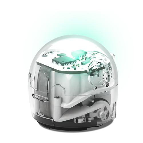
It does however have two built in direct current (DC) motors, meaning it runs a constant voltage level, e.g. 5 volts. While they have two different intended uses, they do operate off the same basic design principle: taking electric energy and turning it into mechanical energy. Both of them have the same basic parts, including a magnet that doesn’t move and coils of copper arranged in an ideal way for the intended application. If you get creative enough you can use them to do the other’s job, but it won’t be as effective as the proper equipment.

When you run electricity through a metal coil it creates a magnetic field which allows it to interact with metallic objects, even if they aren’t magnetic. This allows you to push a speaker cone outward and pull it inward using an audio signal and rotate the output shaft of a DC motor.

Now, because you are creating a magnetic field in the metal coils, there is a vibration created by the formation of the magnetic field which we can sometimes hear, depending on how fast the coils are vibrating. You can even find this phenomenon in everyday electronics that aren’t meant to make sound or movement thanks to the inductor – a coil wrapped around a material (usually in a circular shape) that is used for many different applications to control how electricity flows within a circuit.

Using this information, we can use the tone() function to produce a “square” wave (50% duty cycle, meaning that the voltage is HIGH and LOW for an equal amount of time). Using the ‘PWM output’ pins on an Arduino board (in this case the left and right motor pins: MOTOR_LEFT_PWM and MOTOR_RIGHT_PWM), gives you direct access to the length of the duty cycle of the PWM output measured in hertz (Hz) instead of the duty cycle using the ‘analogWrite()’ function (which adjusts the duty cycle instead).

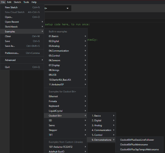
If you upload the OzobotBitPlusFreqSweep sketch included in the demonstrations section of the Bit+ examples to the Bit+, you will be able to hear the range of the DC motors ‘frequency response’ (the range of frequencies that the DC motor will produce an audible sound). Although with the tone() function you can go as high as an unsigned integer will allow (65535Hz), the average human hearing range is 20Hz-20000Hz so you will not be able to hear over 60% of the usable values. And with the consideration of a DC motor not being meant to reproduce audio, the usable range will likely be closer to 25% of the values as the vibration of the coils within the motor get very quiet in frequencies above 15000Hz.

Just because something doesn’t look like it will work on the surface, doesn’t mean that it won’t have an alternate purpose, don’t be afraid to get creative with your sketches!

Happy coding!

You Have Signed Up Successfully

You’ve been added to our mailing list and will now be among the first to hear about new arrivals, big events, and special offers.